
Start with the unattended duty cycle
A remote device may sleep for most of its life yet fail during a short radio transmission, camera startup or actuator movement. Define sleep current, wake frequency, measurement time, communication retries and recovery after a power interruption. These are proposed design scenarios, not claims about an installed BK customer project.
Model average energy and peak power separately
Calculate energy over a representative day, including conversion losses and controller standby consumption. Then test the highest current pulse independently. A pack can have remaining nominal capacity and still reach a device undervoltage threshold during a cold pulse. Record loaded terminal voltage and the instrument minimum input voltage, rather than relying only on an unloaded battery reading.
Use temperature at the cell
A cabinet can lag ambient changes and can also warm in sunlight. Establish the minimum cell temperature after an overnight soak and the maximum during charging or active operation. Public laboratory material shows that cold conditions affect electrochemical behavior and charging controls; it does not define the performance of an unspecified remote monitoring pack. [1]
Compare BK LFP options by measured load
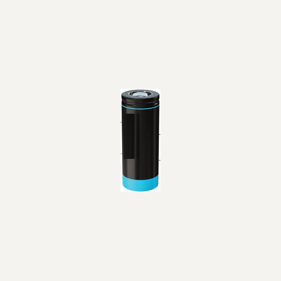
BK-LT18650-1500 is a compact-format evaluation option, while the four BK-LT26650 models offer different capacity and listed rate combinations. In the supplied table, 3200mAh is paired with 5C, 3400mAh with 3C, and 3500mAh and 3800mAh with 1C. A larger capacity number is therefore not automatically the best solution for a high pulse load. Confirm the exact temperature-dependent behavior with the supplier.
Plan replenishment for the worst energy interval
If solar charging is proposed, account for short daylight, snow cover and poor-weather periods without assuming daily full recharge. Keep charging disabled outside the selected cell’s approved charge map, even if discharge is allowed. The design must also address self-discharge, electronics consumption and reserve for delayed maintenance. Obtain model-specific storage limits; they are not supplied in the preliminary BK table.
Design the enclosure and recovery sequence
Review moisture ingress, condensation, connector corrosion and sensor placement. Verify boot behavior after BMS cutoff and charging recovery after the cabinet warms. A cell’s temperature range is not a rating for the radio, seals or electronics. Controlled-heating research illustrates that thermal management requires a system solution rather than a chemistry label alone. [2]
Validate before unattended deployment
Agree test durations, temperature soak, pulse sequence, communication duty and a pass/fail voltage floor. Compare several samples and include aged-pack margins. Use the product links below for the preliminary BK tables, and include a real load trace in the RFQ. No installation pictured or discussed here is asserted to use BK cells.
Sources
- Idaho National Laboratory — EV charging in cold temperatures
- Yang et al. — Fast charging of lithium-ion batteries at all temperatures (original research)
Independent technical discussion. BK-specific figures come from the supplied documents and remain subject to a signed model specification and traceable test report. Neither the public sources nor the photograph candidates establish a customer or manufacturer relationship.